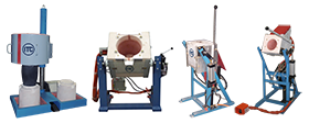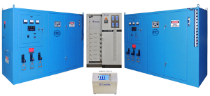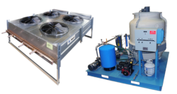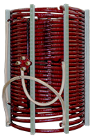
Most induction equipment has fixed furnace drain temperature switches set at 175 °F (79°C).
Restrictions anywhere in the furnace’s water flow path for the furnace coil can and will cause over-temperature conditions. Restrictions can be caused by debris or calcium buildup in water lines, heat exchanger and water-cooled power cables, internal damage to water-cooled power cables such as “bird nesting”, kinking or flattening of the hose. Water-cooled power cables do fail over time and replacement is required. Life span varies depending on the amount of use, water quality, layout, and configuration. Keep in mind that a restriction is a restriction! It does not matter if it is the feed line, drain line, or coil, all will result in Furnace Drain over-temperature alarm or faults.
The use of an induction melting furnace that was not designed for the application or designed for kW output of the induction power supply, modifying water paths can also cause overtemperature issues.
Furnace lining dimensions and proper installation using quality material is also very important, making changes from original design parameters is not recommended and strongly discouraged. Not having a proper amount of refractory “back-up” material will cause overheating and damage to the furnace coil.
Typically, an internal water high-temperature alarm or fault is caused by flow restriction, either in an individual circuit or a heat exchanger. Power supply cabinets can have multiple circuits and it must be determined which of these circuits are overheating, then determine if it is a flow restriction or other cause for the alarm. A broken switch, signal phase condition is just a couple of possibilities. Flow restrictions are caused by debris in the system, electrolysis, and overall poor water quality.
Induction power supplies typically have an “internal closed-loop” water system or an “external closed-loop” water system, some will have a combination of both. Water purity and quality are critical in both systems for the longevity of the induction melting equipment, minimizing maintenance and costly repairs.
An external high-water temperature alarm or fault happens when the process supply water exceeds the temperature switch setpoint, typically 115 °F (46°C) set point. The process water is cooled in a few different ways using open evaporative cooling tower, dry type radiator cooler or air conditioning chiller units. When the efficiency of these coolers decreases process water temperatures increase. There are many reasons for the loss of efficiency, calcium deposits on tube bundles and in heat exchangers are the most common.
An Internal Closed system consists of a circulation pump, expansion tank, and heat exchange designed to cool all internal components and maintain water quality. Low conductivity water is essential to induction power supplies with internal water systems and must be maintained. Read more about types of cooling systems here
High water temp alarms or faults are mostly due to low water flow, either from restrictions in water circuits or not enough water pressure being delivered to the equipment.
Typical induction melting furnace drain temperatures will range from 100°F (37°C) to 150 °F (65°C). ITC induction power supplies monitor all furnace drain temperatures with an auto-reset temperature switch set at 175°F (79°C). Should the induction melting furnace drain temperatures exceed 175 °F (79°C), the temperature drain switch activates, “trips” and opens the electrical safety circuit causing the induction power supply to turn off. The automatic reset temperature switch will reset after the water temperature cools below 165 °F (73°C) allowing the induction power supply to operate again.
After the system is purged of air and with makeup water functioning, the circulating pump suction side pressure will be 12 – 18 psi, the discharge side of the pump will vary and is dependent on the pump curve and how it was spec’d. When the system is overcharged with water, suction side pressure will be higher 20–30 pounds as well as the discharge side. This does not mean more water is flowing and is detrimental to cooling as it generates heat.
Depending on coil design, configurations and application, the requirements vary widely. Below is an example of how to calculate minimum flow requirements:
1 gallon of water for every 25 kW @ 40 PSI.
Example: An induction melting furnace connected to a 200 kW induction power supply requires a minimum of 8 GPM. 200/25 = 8 or 8 GPM @ 40 PSI. This would be the absolute least amount of water flow to cool and depending on configurations more flow may be required due to higher currents present in the coil.


