Contact ITC Support
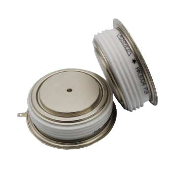
SCR stands for Silicon Controlled Rectifier, a semiconductor device that can carry high current and voltage for many industrial applications. Three-phase SCR bridge rectifiers and inverters are commonly used in induction melting and heating equipment.
What causes SCR’s and diodes to fail in induction melting units?
There are many reasons for SCR’s to fail, here are a few of the most common.
- Excessive temperature
- Misalignment of the devices
- Improper torque of tightening the devices
- Improper or insufficient gate pulse sequences
- Incorrect device for the circuit application
- Loose electrical connections
- Excessive amount of heat sink compound
- R/C Network compromised or inadequate
- Excessive current
- Excessive voltage
- Incorrect parallel diodes
- Condensation
Temperature/Overheating
Inadequate cooling of semiconductors such as SCR and Diodes can and will cause devices to fail prematurely, some in a matter of minutes depending on the amount of current being carried. If you are experiencing recurring device failure it may be caused by a lack of cooling. Check water flow in water-cooled chill blocks, typically it will be around 3.5 GPM at 40 PSI. Keep in mind any restriction in a water path can and will cause problems eventually.
Misalignment
This is one of the most common mistakes maintenance makes when replacing devices.
In most induction equipment, SCR and Diodes are held in a clamp with water-cooled chill blocks, these blocks have alignment centering pins that protrude into a manufacturing dimple in the center of the device. This ensures the device achieves maximum electrical contact surface and cooling. Misalignment of these pins causes the device to not sit flat on the contact surface forcing current to only flow through a small area, arcing between the device and chill block occurs as a result, creating high voltage spikes damaging the SCR internally and eventually failure. A symptom of this will be the induction unit will run fine at lower power levels, and when pushed to near full power have random faults or tripping.
Improper Torque
Improper torque, usually not enough torque, on an SCR or diode clamp can cause tripping issues and shorten the life of devices. Most SCR and diode clamp assemblies have a torque indicator of some sort. Before disassembly to replace a device take note of the indicator position. Over time torques bolts in clamp assemblies can and will stretch and should be checked during regular routine maintenance.
Improper or Insufficient Gate Pulse
Specialty electronic test equipment is required to detect and determine proper gate pulse width and amplitude, contact ITC support for more details.
Incorrect Device
Not all devices are created equal, just because the device looks the same, same size and similar but not exact markings do not make them the same. Only use known correct devices in your unit, substituting devices may cause other failures. Contact ITC support for proper devices for your equipment, we have the knowledge to supply the proper device for all manufacturers ’ equipment.
Loose Electrical Connections
Loose connection anywhere in the unit can arc and cause high voltage spikes, this can cause electrical noise within the unit misfiring logic circuits and gate signals to SCR’s. weak or improper gate signals can and will shorten life expectancy of SCR’s. The white and red wires connecting directly to the SCR over time can come loose creating a poor electrical connection interfering with gate signals. The white wire carries the gate signal and if loose will cause erratic signals, tripping and over time device failure.
Heat Sink Compound
When installing an SCR or diode a very thin, almost translucent layer of heat sink compound should be used. This is used to transfer heat from the device to the heat sink. Some heat sink compounds are comprised of dielectric grease, an electrical insulator, an excessive amount of this type of compound should be avoided.
R/C or Snubber Network
R/C Networks stands for capacitor resistor network. It is designed to snub, or clip voltage spikes generated across the SCR protecting the device from excessively high voltage spikes. Should this R/C Network be compromised from loose connections, cracked solder joints, or altered component specifications high voltage spikes will occur causing damage or failure to the SCR.
Excessive Current
SCR’s are designed to carry X amount of current at X frequency, should the parameters be exceeded damage and failure will occur. Most logic circuits monitor current carried by the SCR and have a limit set to protect the device. Should this limit be changed or fail, SCR failure may occur.
Excessive Voltage
Over volt conditions on a SCR will cause damage and failure over time. Proper inverter design is key for the longevity of SCR and diodes, altering or modifying this design is never a clever idea. Loose connections anyplace in the power circuit can cause damaging high voltage spike to travel through an SCR resulting in device failure. SEE R/C Network.
Incorrect Parallel Diode
Inverters for induction power supplies are specifically designed and require specific devices. Modifying or changing the circuit or components will result in failure. Contact ITC for correct devices for your equipment.
Condensation
Just as not enough cooling for devices will cause damage, having too cold of water cooling below dew point creating condensation inside the cabinet, water on diodes and SCR’s or the clamps will cause damage. SCR and Diode assemblies must be clean and dry to prevent arcing within the clamp.

